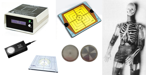
Diagnostic Radiology
Please click the product you want to learn more about:
i. Beam Measurement
QUART didoCT
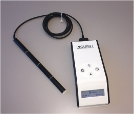
Pencil Chamber Meter for CT Applications
The QUART didoCT meter is designed for easy and precise dose-width product measurements.
The meter does not require any pre-setting procedure for direct reading of DWP, rate and time parameters. Its detector part is based on solid-state technology. Unlike conventional ion chambers, the QUART didoCT is not affected by variations in environmental temperature or air pressure and does not require correction.
The didoCT is equipped with a backlit display to assure swift readings even in darkened environments. To provide the ability to track generator characteristics, the dose or DWP rate is refreshed continuously on the meter display while the measurement is running.
The meter is powered by a rechargeable battery. One charge is sufficient to last approximately 80 hours of continuous use. Recharging the meter until full takes only between 3–4 hours. A warning will appear on the display when the battery charge is running low.
Additional Features
- Measures kVp, kVeff, mA, mAS, exposure time, dose, HVL
- Easy to use
- kV measurement is non-invasive
- AC or DC x-rays
- High accuracy
- mA invasive or non-invasive (option)
- Two year warranty
USB Tablet Display
- 7 inch Tablet display for reading outside x-ray room
- Tablet holds stored readings
- Export data to spreadsheet
- Email or transfer data to computer
- Display graph of X-ray waveform
Typical Applications
- Verification of peak X-ray voltage
- Constancy checks
- Calibration of X-ray
- Quality assurance
- Measurement of exposure time
- Half value layer determination
- Troubleshooting and repair of X-rays
- Maintain quality of X-ray
Model 870
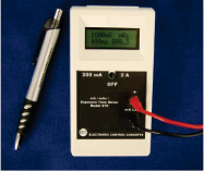
mA, mAs & Exposure Time Meter
The Model 870 is a solid-state, digital instrument designed to assess the performance of medical X-ray generators. This instrument measures and displays mA, mAs, and exposure time for each X-ray exposure and can be used to test dental, radiographic, and fluoroscopic X-ray units. This is a new state of the art instrument with many advanced features. For example, entering correction factors for different types of X-ray waveforms is not required since the Model 870 has the capability of automatically determining the type of X-rays being measured. In addition mA, mAs and exposure time are displayed and stored for each X-ray exposure further minimizing the number of X-ray exposures.
Model 815
Digital kVp Meter and Exposure Timer
The Model 815 is a versatile, multipurpose digital kVp meter, optimized for dental X-rays but also usable on conventional and fluoroscopic X-rays. In addition, it measures the time duration of X-ray exposure.
Operation can be learned in minutes: simply place the Model 815 in the beam and make an exposure. The large display is easily readable from outside the X-ray room and the alphanumeric messages provide easy to understand operational and diagnostic status.
Analog waveform output for an oscilloscope is provided for waveform analysis – half wave, full wave, DC and 3 phase.
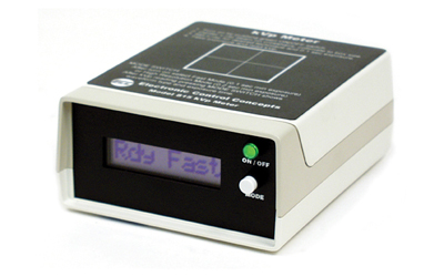
Model 8700
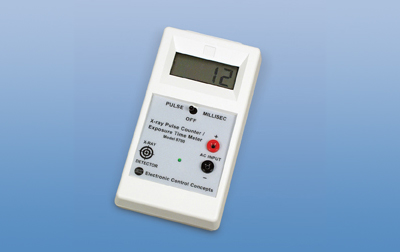
X-Ray Pulse Counter & Exposure Time Meter
The Model 8700 is a versatile digital X-ray pulse counter and exposure time meter. It measures the time or duration of radiation output produced by a wide variety of X-ray generators.
For direct measurement of exposure from the X-ray head, simply place the 8700 under the head and make an exposure. The 8700 is "self-resetting". There is no need to reset the instrument after each reading. The reading is stored after each exposure, until the next exposure.
When testing X-ray timers and controls, the time of the relay contact closure can be measured using the AC input feature. When used with DC, capacitor discharge and 3-phase X-ray, exposure time is measured in milliseconds.
Typical applications include: verification of X-ray exposure time, calibration of X-ray timer, quality assurance, measurement of exposure, direct measurement of timer accuracy and analysis of X-ray malfunctions.
An optional remote sensor is available to allow use of the 8700 at distances of up to 12 feet away from the X-ray machine.
QUART didoEASY Series
Easy-to-Use Precision Dosimeters
The QUART didoEASY meters are designed for precise dose measurements. The meters do not require any pre-setting and measurement results are quick and easy.
Use the didoEASY R for all of your R+F all measurements, the didoEASY M for Mammography measurements, and the didoEASY MR for Dental, R+F, and Mammo measurements. In addition, the didoEASY meter series also measures the integrated dose-width product (DWP) for dental panoramic units.
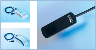
ii. Diagnostic Ion Chambers
Model N23344
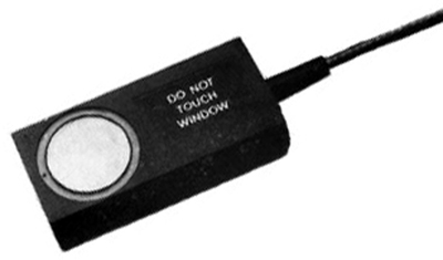
Soft X-Ray Ionization Chamber
The Model N23344 soft X-ray ionization chamber is similar in design to the Model N23342 but featuring a volume that is ten times greater. It is intended for dose measurements in mammography and skin therapy. It can be used in air or in solid phantoms.
The acrylic chamber body has back-scatter properties similar to skin, and the thin window permits accurate measurements of soft X-ray radiation. The energy response is exceptionally flat over the 10keV to 30keV range.
iii. Phantoms
Model 76-432
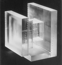
CT Spiral Phantom
The accurate indexing capability and exceptional image quality of computed tomography (CT) scanners not only guarantee the object’s location, size and shape, but also improve the diagnosis accuracy. The index and performance parameters of CT scanners cannot be confirmed without objects of known specifications. The Model 76-432 CT Spiral Phantom provides specific details necessary to confirm the integrity of both conventional and spiral scanning. What makes the phantom unique is that it allows the user to visually evaluate all test results in their image displays.
The phantom consists of five acrylic plates of different sizes, all affixed to a flat rectangular base. Specific hole patterns are drilled on each side of these plates. When imaging, the holes within the X-ray field will appear in the phantom images. By the appearance of the holes, both index and performance parameters can be confirmed qualitatively and quantitatively.
PIXY®
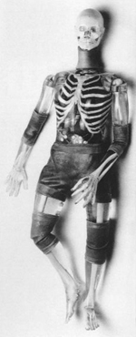
Anthromorphic Training/Teaching Phantom
PIXY® is used to demonstrate anatomy and evaluate positioning and imaging techniques, including kVp, mAs, contrast, optical density, OFD and TFD. Radiographs of PIXY® are optically equivalent in density and contrast to human patients. PIXY® permits unlimited exposures and tolerates trainee errors.
Anatomy – PIXY® shoulders have ball and socket joints; elbows and knees flex 90° and 100°. Hips flex 130° with 30° hyperextension.
A “frog" position is made possible by lateral flexion at the hips. The right hand is molded with fingers positioned for an AP view, while the left hand is in an oblique-lateral position. The left foot is in full plantarflexion; the right foot is in neutral position.
Neck vertebrae C1, C2, C6 and C7 were converted to mechanical nylon joints because the educators in the field prefer full positioning capabilities for the head. The design permits the remaining neck vertebrae to be fixed in a normal position, while assuring a full range of head motion.
PIXY® contains abdominal and pelvic organs: stomach, gallbladder, urinary bladder, kidneys, rectum and sigmoid flexure. These are air-filled, but accept water or contrast media and can be easily flushed after use. Custom fractures and custom pathologies are optional.
Materials – Highly-detailed polymer skeletons which reproduce shape, mass density and attenuation co-efficients of the cortical bone and spongiosa, allow continuous production of phantoms, instead of sporadic production due to limited availability, variable size and uncertain chemical composition of human skeletons. Nevertheless, human skeletons are available for users who desire them. There is a surcharge to cover the high cost of scarce natural skeletons and for added labor needed to rework them to fit PIXY® molds.
The matching of skeletons and soft tissues permits external and bony landmarks to coincide. The position of bones within the soft tissues is anatomically correct.
The detail cast into skeletons is considered a triumph of sculptural moldmaker’s craft. The skull, for example, has frontal and sphenoidal sinuses, ethmoidal and mastoid air cells and the auditory ossicle. Bone structures are radiographically visible.
Soft Tissues – PIXY® is available in opaque or transparent tissue equivalent materials. The transparent PIXY® has visible organs and skeleton except at the hips, knees, and elbows, which are opaque because, as on opaque PIXY®, latex coverings are needed to retain tissue-equivalent gels for soft-tissue continuity at these articulations. Two-ply coverings protect against gel leakage.
Standard PIXY® lungs are molded of tissue-equivalent foam with a mass density of inflated human lungs (0.30g/cc). They are connected to the oronasal cavity by the stem bronchi and trachea. The oro-nasal pharynx is filled with a nearly air-equivalent foam.
Optional animal lungs, which duplicate the intricate detail of the vascular trees, are available. These lungs are fixed in the inflated state and molded to conform to the pleural cavities of the phantom.
The pulmonary arteries are injected with the blood-equivalent plastic. In addition, low-, medium-, and high-contrast material may be selected by the user.
Sectional Phantoms
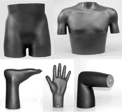
Anthromorphic Training/Teaching Phantom
Sectional phantoms are used when you require a human subject to train radiographers in the use of radiography equipment. The complete sectional phantom set and the individual sectional phantoms may be used repeatedly to learn how various positions and techniques will produce a variety of radiographic images.
A natural human skeleton is first reconstructed into the sectional molds of an average-sized male patient. With the bones set in place, the mold is filled with a specially formulated urethane material, the same as is utilized in the RANDO® phantom, which simulates the density of tissue and organs. This opaque material duplicates the X-ray absorbency, atomic number, and specific gravity of soft human tissue. Because the RANDO® material is virtually indestructible, these sectional phantoms will withstand substantial impact and continuous handling without damage.
Only natural skeletons are used in these anthropomorphic phantoms. Many skeletons reflect natural human characteristics such as lack of symmetry and distorted joints. As the technicians reconstruct the skeleton, minor adjustments may be made to facilitate positioning within the mold. The natural characteristics and the adjustments should not present any problems in the use of the phantom.
Model SK150, Head
The skull and cervical vertebrae are cast into the head phantom with an internal air cavity to represent the oral, pharynx and trachea anatomy. It is also available without the cervical vertebrae.
Model SK200, Thorax
The thorax phantom contains the chest and shoulder skeletal structures including the upper third of the humerus. The lungs’ lower density is duplicated with a special material, the same material as used in the RANDO® phantom lungs, which has an atomic number and specific gravity of human lungs at a median respiratory state. This material is formed to the contours of the rib cage.
Model SK250, Lower Torso
The lumbar vertebrae, pelvis and upper third of the femur are cast into the lower torso phantom. A hollow cavity reproduces the interior of the sigmoid flexure with the diverticulum and rectum. This cavity is connected to the surface by a duct that is sealed with an O-ring screw cap. The cavity may be filled with contrast media. It is not discernible when filled with water.
Models XA235-L & XA235-R, Left and Right Elbows
The elbow phantoms contain the lower third of the humerus and the upper third of the radius and ulna. The right elbow has a 90° flexion and the left elbow is extended.
Models XA231-L & XA231-R, Left and Right Hands
The hand phantoms contain the lower third of the radius and ulna along with the carpal and finger bones. The left hand is pronated and the right hand is relaxed.
Models XA245-L & XA245-R, Left and Right Knees
The knee phantoms contain the lower third of the femur, the upper third of the fibula and tibia, and the patella. The right knee has a 90° flexion and the left knee is extended.
Models XA241-L & XA241-R, Left and Right Feet
The foot phantoms contain the lower third of the fibula and tibia along with the tarsal and toe bones. The left foot is relaxed and the right foot is in plantar position.
Model SP500, Complete Sectional Phantom
The complete set consists of 11 sectional phantoms including head, thorax, lower torso and the left and right elbows, hands, knees and feet. All come packed in a convenient wooden storage case.
RANDO® is a registered trademark of the Phantom Library
iv. Test Tools
Mammo Phototimer
Consistency Test Tools
A mammographic unit’s Automatic Exposure Control should be capable of maintaining optical density within ±0.15 OD as the voltage is varied from 25 to 35 kVp, and as breast thickness is varied from 2 to 8 cm for each technique. Test images taken of uniform phantoms of varying thicknesses should not differ by more than ±0.30 OD from each other. These tests should be carried out over the kVp range customarily used by the mammography center.
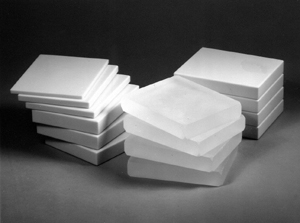
The phototimer consistency test tools are available in two materials: acrylic and, for more accurate results, breast tissue equivalent BR-12 material.
BR-12 is a designation (D.R. White et al.) of certain epoxy resin formulations that react to X-rays in the mammographic energy range (15-30 keV) in the same manner as the human tissue. The tissue simulation properties for these slabs are maximized at 20 keV (28kVp±). The glandular equivalency of this material is 45% in the mammographic range.
X-Ray Test Tools 1
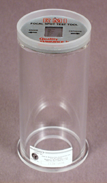
112B Focal Spot Test Tool
The focal spot size of an X-ray tube is of crucial importance in determining the detail of an X-ray image. The Focal Spot Test Tool was developed to allow easy and accurate interpretation of the effective focal spot size of radiographic X-ray tubes. The Model 112B consists of a metal target with twelve bar pattern groups. Each group consists of six slots with three slots perpendicular to the other three. The sizes and spacing of the slots in the 12 groups decrease by steps of 16% from 0.84 LP/mm to 5.66 LP/mm. The test pattern is mounted in the center of an acrylic disc 7.6cm in diameter that contains a lead shield. The Model 112B is easier to interpret than the pinhole image or a star pattern for effective focal spot measurements.
117 Radiographic Aluminum Step Wedge
This step wedge is constructed of homogeneous, high-purity aluminum and is designed to provide incremental exposures to X-ray film by the increased aluminum thicknesses in each step. The Model 117 provides a useful means of comparing the characteristic curve of various film-screen combinations, mAs reciprocity, and, if done very carefully, sensitometry. For sensitometry totally independent of X-ray generator variations, use a dedicated sensitometer/densitometer.
118 Mammographic Aluminum Step Wedge
Constructed of homogeneous, high purity aluminum, this step wedge provides incremental exposures to mammographic X-ray film by the increased aluminum thicknesses in each step. The step wedge provides a useful means of comparing the characteristic curve of various film-screen combinations, mAs reciprocity and, when carefully performed, sensitometry. For sensitometry totally independent of X-ray generator variations, use a dedicated sensitometer/densitometer.
X-Ray Test Tools 2
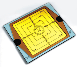
132 Tomographic Test Tool
Designed to test the imaging capabilities of the tomographic system, the Model 132 can be used to:
- Determine the location of the cut plane.
- Determine the thickness of the cut.
- Test the overall resolution of the cut plane.
- Test the X-ray exposure uniformity.
- Determine the path of the beam during exposure, for both linear and multi-directional units.
141 & 141H High-Contrast Resolution Test Tools
One important measure of your fluoroscopy system is its high contrast resolution. This test can assess the resolving power of your system and can be accomplished easily with Models 141 and 141H.
Both high-contrast resolution test tools consist of eight patterns of copper wire mesh in a pie shape. Each is labeled with lead numbers for easy visualization. Model 141 is used for standard radiographic systems with resolutions between 16 and 60 mesh, and Model 141H is used for systems with higher resolution such as those used in cardiology suites, where resolution is between 60 and 150 mesh.
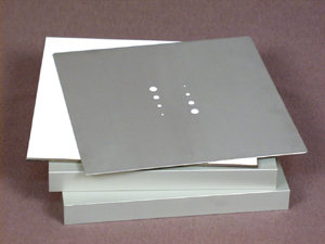
142D & 143D Film/Screen Contact Test Tools
Inspection of cassettes for good film/screen contact and screen integrity is an important but often overlooked quality control procedure. Poor film/screen contact can be the reason for areas of increased density, reduced density and blurring.
X-Ray Test Tools 3
151 Low-Resolution Test Tool
An Automatic Brightness Control (ABC) for fluoroscopy compensates for variation in patient thickness, X-ray field size, image intensifier magnification modes and other variations of the system. The Model 151 Low-Contrast Resolution Test Tool evaluates the system’s ability to compensate for these variations while maintaining good contrast and detail.
The Model 151 consists of two aluminum blocks, one lead blocker and an aluminum resolution plate with two sets of decreasing diameter holes. Other tests performed are table top exposure rate in R/min for fluoro units and the phototimer performance of spot film devices.
144 Grid Alignment Test Tool
The Model 144 is designed to test proper grid alignment with respect to the central ray of the X-ray tube. Grid misalignments, such as lateral decentering or tilting of the grid, are not easily recognized and can have an effect on image contrast as well as increasing patient dose. These types of misalignments can only be detected through regular quality control testing with the Model 144.
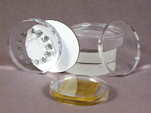
161B Collimator Test Tool & 162A Beam Alignment Test Tool
The Model 161B is designed to evaluate the collimator light field and X-ray field congruence. It is constructed of brass so that centimeter etchings on its surface can give a direct ruled dimension on the radiograph. It is calibrated to show misalignments to within 0.5 cm.
The Model 162A provides a simple test of the X-ray beam’s alignment. When used with the Model 161B, misalignments of 1% and 2% can be visualized. It is constructed as a plastic cylinder with one steel ball at each end. If everything is in alignment, the steel balls will be superimposed on the radiograph.
X-Ray Test Tools 4
1151 Radiographic Contrast/Detail Test Tool
A useful method of assessing the overall image quality of a fluoroscopy system is by defining its ability to detect small objects with small differences in contrast from the background.
The Model 1151 consists of an aluminum plate with a 10 x 10 matrix of holes that vary in diameter and depth. For a hole diameter, the depth of the hole which can just be visualized is defined as the contrast for that diameter. A contrast detail curve of the fluoroscopic system can be established by plotting the diameter of the hole vs the depth of the hole that is being visualized.
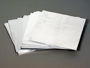
AFS-1 Aluminum HVL Attenuator Set
Consists of sixteen 10 x 10cm absorbers of various thicknesses; six of 1mm, two of 0.5mm, four of 0.1mm and four of 0.05mm made of 1100 aluminum with a purity of 99%. Total thickness of the set is 7.6mm.
07-434 High-Purity Aluminum HVL Attenuator Set
When doing HVL measurements with a mammography unit, it is recommended that highest-purity aluminum be used. The set consists of five high purity (99.99%) aluminum filter, 10 x 10cm, 0.1mm thick, which permit more accurate half-value layer determination on mammography machines.
07-431 Copper HVL Attenuator Set
For HVL determination of high-range X-ray generators (140 to 400 kVp). Set consists of ten 10 x 10cm absorbers, including four of 1mm, two of 0.5mm, and four of 0.1mm, for a total thickness of 5.4mm.
X-Ray Test Patterns
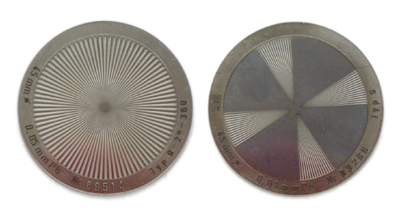
Star Test Patterns
Focal spot size can be determined by observing the regions of blurring which occur when the pattern is radiographed by an X-ray source of finite dimensions. Radiation from different areas of the focal spot will cause a periodic blurring of the pattern due to penumbra effects. Knowledge of the geometric factors and the distance from the center of the pattern to the region where blurring occurs will permit the calculation of the focal spot size.
The star patterns listed below are handmade, ultraprecision types.
07-555 Resolution X-Ray Test Pattern
Resolution X-Ray Test Pattern is specifically designed for evaluation of focal spot performance protocol in Mammography.
It is now being suggested that a resolution test pattern from 5-20 LP/mm be used to evaluate the condition of the focal spot. Instead of making focal spot measurements that can be ambiguous, an accurate determination of the X-ray tube’s resolution ability can be measured by using this test pattern. The Model 07-555 is manufactured from 0.02mm thick gold foil, 25mm long and 10mm wide. The pattern has 13 segments, from 5 LP/mm to 20 LP/mm. Radio-opaque numbers indicate the resolution (in LP/mm) of each group.
MC-1 Pocket Optical Comparator
Ideal for checking small parts, linear measurements, hole diameters, thread sizes and slit camera images. Unlike lower priced comparators with only a simple lens, the MC-1 incorporates a triplet lens. It provides an extremely flat field over the entire reticle area. The clear, acrylic cell allows the outside light to illuminate the subject. The comparator reticle is different from ordinary reticles in that the fine ink-filled markings are on the outside of the reticle. This is done so that the reticle scales are always in direct contact with the object and you always get optimum focus, freedom from parallax and accurate measurements. The scale reticle is optical glass with a pigment-filled pattern, 20mm long with 0.1mm per division.
Model 120-20 Visi-X
X-Ray/Light Field Alignment Tool
The Model 120-20 Visi-X is a new concept in Quality Control and Service. It is a cassette-shaped instrument for checking the light and radiation field coincidence on x-ray equipment. The Visi-X can also be used for checking the centering of the Bucky tray.
The Visi-X is constructed of acrylic and its operation is based on the long persistence afterglow principle of its phosphor screen. The phosphor is non-radioactive and is confined by acrylic plates. A daylight filter protects the phosphor from unwanted excitation from light sources.
To use, simply darken the X-ray room and place the Visi-X under the X-ray tube. Adjust the light field and make the exposure. The radiation field will immediately be visualized by the glow of the special phosphor compound. This afterglow will last for several minutes. Misalignments as little as ±0.5mm will be clearly shown on the built-in scale. No film is needed, therefore no time is lost going back and forth to the film developer.
When viewing the ordinary intensifying screens you will expose yourself to unnecessary radiation. With the Visi-X, you do not have to be present in the X-ray room, therefore there is no radiation hazard.
The Visi-X will conveniently check the light and radiation field coincidence on your conventional diagnostic, dental and mammographic X-ray equipment. A magnetic lock allows Visi-X to be used in vertical and upside-down positions.